
ISO 6603-2-2000 “Materiale plastice plastice dure determinarea comportamentului la impact la perforare – Parte 2: Test de impact al instrumentului”
prefaţă
ISO (Organizația Internațională pentru Standardizare) este o alianță globală a organismelor naționale de standardizare (organismele membre ISO). Elaborarea standardelor internaționale se realizează de obicei prin intermediul comitetelor tehnice ISO. Fiecare instituție membră interesată de un subiect pe care a fost înființat un comitet tehnic are dreptul de a fi reprezentată în respectivul comitet. Organizațiile internaționale guvernamentale și neguvernamentale care au legătură cu ISO sunt, de asemenea, implicate în această activitate. ISO lucrează îndeaproape cu Comisia Electrotehnică Internațională (IEC) pe toate problemele de standardizare electrotehnică.
Standardele internaționale sunt elaborate în conformitate cu regulile prevăzute în partea 3 din Directiva ISO/IEC.
Proiectele de standarde internaționale adoptate de Comitetul Tehnic vor fi transmise organelor membre pentru vot. Publicarea ca standard internațional necesită aprobarea de cel puțin 75% a organelor membre.
Please note that some elements of this section of ISO 6603 May be the subject of patent rights. ISO nu este responsabil pentru identificarea unuia sau a tuturor acestor brevete.
Standardul internațional ISO 6603-2 a fost dezvoltat de Comitetul Tehnic ISO/TC 61, Materiale plastice, Subcomisia SC 2, Mechanical Properties.
The second edition cancelled and replaced the first edition (ISO 6603-2:1989), which had been technically revised.
ISO 6603 consists of the following parts under the general heading Plastics – Determinarea comportamentului la impact la perforare a materialelor plastice rigide:
— Parte 1: Testare de impact non-instrumentală
— Parte 2: Instrumental impact testing
The appendices A to E of this part of ISO 6603 are for reference only.
ISO 6603-2-2000 “Materiale plastice plastice dure determinarea comportamentului la impact la perforare – Parte 2: Test de impact al instrumentului”
1 gamă
Această parte a ISO 6603 specifies a test method for determining puncture impact properties of rigid plastics in the form of flat specimens using instruments that measure force and deflection. Applies if a force-deflection or force-time plot recorded at a nominal constant firing pin speed is necessary to characterize impact behavior in detail.
If ISO 6603-1 is sufficient to characterize the impact behavior of plastics by impact failure energy thresholds based on many samples, ISO 6603-1 May be used.
Această parte a ISO 6603 is not intended to explain the mechanisms that occur at each particular point in the force-deflection diagram. These explanations are the task of scientific research.
Note also article 1 of ISO 6603-1:2000.
ISO 6603-2-2000 “Materiale plastice plastice dure determinarea comportamentului la impact la perforare – Parte 2: Test de impact al instrumentului”
2 referințe normative
The following normative documents contain provisions which, by reference herein, constitute the provisions of this part of ISO 6603. Pentru referințe datate, nu se vor aplica revizuiri sau modificări ulterioare ale acestor publicații. in orice caz, Parties to an agreement based on this part of ISO 6603 are encouraged to investigate the possibility of applying the latest version of the following normative documents. Pentru referințe nedatate, the latest version of the normative document referred to applies. Members of ISO and IEC maintain a register of international standards currently in force.
ISO 2602:1980, Statistical interpretation of test results – mean Estimators – confidence intervals.
ISO 6603-1:2000, Materiale plastice. Determination of puncture impact behavior of rigid plastics. Parte 1: Non-instrumental impact tests.
3 Termeni și definiții
For the purposes of this part of ISO 6603, se aplică următorii termeni și definiții.
3.1 Impact velocity
The speed of the firing pin relative to the support at impact
Notă 1: The impact velocity is expressed in meters per second (Domnișoară).
3.2 Force F
The force exerted by the firing pin on the specimen in the direction of impact
Notă 1: Force is expressed in Newtons (N).
3.3 Deflection l
The relative displacement between the firing pin and the specimen support starts from the first contact between the firing pin and the specimen
Notă 1: Deflection is expressed in millimeters (mm).
3.4 Energy
Energy used to deform and penetrate the specimen up to the deflection L
Notă 1: Energy is expressed in joules (J).
Notă 2 The energy is measured as the integral of the force-deflection curve from the point of impact to the deflection l.
ISO 6603-2-2000 “Materiale plastice plastice dure determinarea comportamentului la impact la perforare – Parte 2: Test de impact al instrumentului”
3.5 Maximum power FM
The most power that occurs during the test
Notă 1: The maximum force is expressed in Newtons (N).
3.6 Deflection lm at maximum force
Deflection at maximum force FM
Notă 1 Deflection at maximum force is expressed in millimeters (mm).
3.7 Energy to maximum strength
The energy expended at maximum force reaches deflection lM
Notă 1: The most powerful energy is expressed in joules (J).
3.8 Puncture deflection lP
The force is reduced to half the deflection of the maximum force F M
See Figures 1-4 și 3.9 notes.
Notă 1 Puncture deflection is expressed in millimeters (mm).
3.9 Puncture energy
Energy expended until the puncture deflects lP
See Figures 1 through 4 and note 2.
Notă 1: Puncture energy is expressed in joules (J).
Notă 2 A probe mounted at a distance from the impact tip records the friction force acting between the cylindrical part of the firing pin and the piercing material when testing hard materials. The corresponding friction energy should not be included in the piercing energy, so the piercing energy is limited to that deflection, where the force drops to half of the maximum force FM.
ISO 6603-2-2000 “Materiale plastice plastice dure determinarea comportamentului la impact la perforare – Parte 2: Test de impact al instrumentului”
3.10 Impact Failure
Mechanical properties of the material to be measured, which may be of one of the following types (Vezi nota) :
A) YD yIELDING (zero slope at maximum power), then DEEP yielding
b) YS yIELDING (Zero slope at maximum power) Apoi (at least partially) cracked the S bench
c) yIELDING of Yu (zero slope at maximum power) Then u unstable cracking
d) no yielding for new features
Notă 1: A comparison of Figures 2 și 3 shows that puncture deflections l, P and puncture energy EP are the same for failure types YS and YU. As shown in Figure 4, in the case of failure type YU, the deflection and energy values are the same at maximum and puncture. For complex behaviour, vezi Anexa A.
Figure 1 — An example of a force-deflection diagram of the typical appearance of a specimen after deep drawing and testing (using lubrication) through yield (zero slope at maximum force)
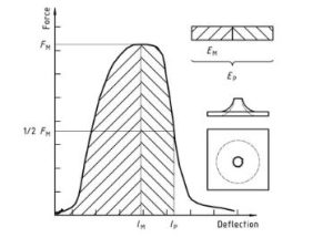
Materiale plastice – Determinarea comportamentului la impact la perforare a materialelor plastice rigide – Parte 2: Instrument impact test Diagram 1
Figure 2 — Example force-deflection plot of failure by yield (zero slope at maximum force), followed by steady crack growth, and typical appearance of the specimen after testing (using lubrication)
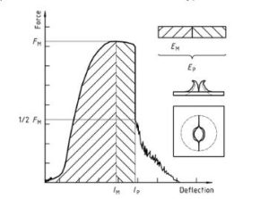
Materiale plastice – Determinarea comportamentului la impact la perforare a materialelor plastice rigide – Parte 2: Instrument impact test diagram 2
Figure 3 — Examples of force-deflection plots through yield (zero slope at maximum force) and typical appearance (lubrication) failure of a tested specimen
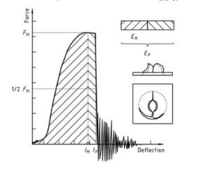
Materiale plastice – Determinarea comportamentului la impact la perforare a materialelor plastice rigide – Parte 2: Instrument impact test diagram 3
Note that the natural vibration of the force detector can be seen after the unstable cracking (firing pin and weighing sensor).
Figure 4 — An example force-deflection diagram of an unyielding failure followed by unstable crack growth and a typical appearance of the specimen after testing (using lubrication)
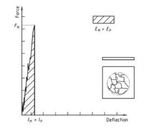
Materiale plastice – Determinarea comportamentului la impact la perforare a materialelor plastice rigide – Parte 2: Instrument impact test diagram 4
Doar secțiunea de informații standard este publică. Pentru a vedea conținutul complet, trebuie să achiziționați standardul prin canalele oficiale.