
ИСО 6603-2-2000 “Пластика – Determination of puncture impact behaviour of rigid plastics – Парт 2: Instrument impact test”
увод
ИСО (Међународна организација за стандардизацију) је глобални савез националних тела за стандардизацију (Тела чланица ИСО). Развој међународних стандарда се обично спроводи преко ИСО техничких комитета. Свака институција чланица заинтересована за предмет за који је основан технички комитет има право да буде заступљена у тој комисији. Међународне владине и невладине организације које су у вези са ИСО такође су укључене у овај посао. ИСО блиско сарађује са Међународном електротехничком комисијом (ИЕЦ) о свим питањима електричне стандардизације.
Међународни стандарди се израђују у складу са правилима датим у ч 3 ИСО/ИЕЦ директиве.
Нацрт међународног стандарда који је усвојио Технички комитет биће прослеђен телима чланицама на гласање. Објављивање као међународни стандард захтева одобрење најмање од стране 75% институција чланица.
Please note that some elements of this part of ISO 6603 May be the subject of a patent right. ИСО није одговоран за идентификацију било ког или свих таквих патената.
Међународни стандард ИСО 6603-2 was developed by the Technical Committee ISO/TC 61, Пластика, Subcommittee SC 2, Mechanical Properties.
ИСО 6603-2-2000 “Пластика – Determination of puncture impact behaviour of rigid plastics – Парт 2: Instrument impact test”
The second edition cancels and replaces the first edition (ИСО 6603-2:1989), which has been technically revised.
ИСО 6603 састоји се од следећих делова, under the general heading Plastics – Determination of puncture impact behaviour of rigid plastics:
– Парт 1: Non-instrumental impact testing
– Парт 2: Instrumented impact testing
Appendices A to E of this part of ISO 6603 are for information purposes only.
1 Домет
Овај део ИСО-а 6603 specifies a test method for determining the puncture impact properties of rigid plastics in the form of flat specimens using instruments that measure force and deflection. This applies if a force-deflection or force-time plot recorded at a nominal constant firing pin speed is necessary to characterize impact behavior in detail.
ИСО 6603-1 can be used if ISO 6603-1 is sufficient to characterize the impact behavior of plastics by an impact failure energy threshold based on many samples.
The purpose of this part of ISO 6603 is not to explain the mechanisms that occur at each particular point on the force-deflection chart. These explanations are the task of scientific research.
Note also Article 1 of ISO 6603-1:2000.
ИСО 6603-2-2000 “Пластика – Determination of puncture impact behaviour of rigid plastics – Парт 2: Instrument impact test”
2 Normative references
The following normative documents contain provisions that, by reference herein, constitute the provisions of this part of ISO 6603. За датиране референце, any subsequent revisions or amendments to these publications will not apply. Међутим, Parties to agreements based on this part of ISO 6603 are encouraged to investigate the possibility of applying new versions of the following normative documents. For undated references, a new version of the standard-setting document referred to applies. ISO and IEC members maintain a register of currently valid international standards.
ИСО 2602:1980, Statistical interpretation of test results – mean estimation – confidence intervals.
ИСО 6603-1:2000, Пластика. Determination of puncture impact behavior of rigid plastics. Парт 1: Non-instrumental impact tests.
3 Terms and definitions
For this part of ISO 6603, the following terms and definitions apply.
3.1 Impact velocity
The speed of the firing pin relative to the support at the time of impact
Белешка 1: The impact velocity is expressed in meters per second (m/s).
3.2 Force F
The force exerted by the firing pin on the specimen in the direction of impact
Белешка 1: Force is expressed in Newtons (Н).
3.3 Deflection l
The relative displacement between the firing pin and the specimen holder begins with the first contact between the firing pin and the specimen
Белешка 1: Deflection is expressed in millimeters (мм).
3.4 Energy
The energy expended to deform and penetrate the specimen up to the deflection L
ИСО 6603-2-2000 “Пластика – Determination of puncture impact behaviour of rigid plastics – Парт 2: Instrument impact test”
Белешка 1: Energy is expressed in joules (J).
Белешка 2: The energy is measured as the integral of the force-deflection curve from the point of impact to the deflection l.
3.5 Maximum Power FM
The test process occurs with maximum force
Белешка 1: Maximum force is expressed in Newtons (Н).
3.6 Deflection lm at maximum force
Deflection at maximum power FM
Белешка 1: Deflection under maximum force is expressed in millimetres (мм).
3.7 Energy to maximum power
The energy expended at maximum force reaches deflection lM
Белешка 1: The most powerful energy is expressed in joules (J).
3.8 Puncture deflection lP
The force is reduced to half the deflection of the maximum force F M
See Figures 1-4 and Note 3.9.
Белешка 1: Puncture deflection is expressed in millimeters (мм).
ИСО 6603-2-2000 “Пластика – Determination of puncture impact behaviour of rigid plastics – Парт 2: Instrument impact test”
3.9 Puncture Energy
The energy consumed until the puncture deflects lP
See Figures 1-4 and note 2.
Белешка 1: The puncture energy is expressed in joules (J).
Белешка 2: When testing hard materials, a probe mounted at a distance from the impact tip can record the friction force acting between the cylindrical part of the firing needle and the piercing material. The corresponding friction energy should not be included in the piercing energy, so the piercing energy is limited to that deflection, where the force drops to half of the maximum force FM.
3.10 Impact Failure
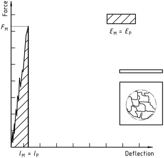
The mechanical properties of the material to be measured may be of one of the following types (see note) :
| а) | YD | yIELDING(Zero slope at maximum force), followed by DEEP drawing |
| б) | YS | (Zero slope at maximum force) then (at least partially) the S table cracks |
| ц) | yu | yIELDING(Zero slope at maximum force) and then u unstable cracking |
| д) | New function | no yielding |
ИСО 6603-2-2000 “Пластика – Determination of puncture impact behaviour of rigid plastics – Парт 2: Instrument impact test”
Белешка 1: A comparison of Figures 2 и 3 shows that puncture deflection lP and puncture energy EP are the same for failure types YS and YU. As shown in Figure 4, in the case of failure type YU, the deflection and energy have the same values at the maximum and at the puncture. For complex behaviour, see annex A.
Figure 1 – An example of a force-deflection diagram of the typical appearance of a specimen after yielding (zero slope at maximum force) followed by deep drawing and testing (using lubrication)
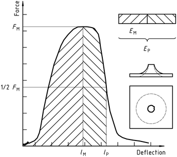
Figure 2 – Example force-deflection diagram of failure by yield (zero slope at maximum force), followed by steady crack growth, and typical appearance of the specimen after testing (using lubrication)
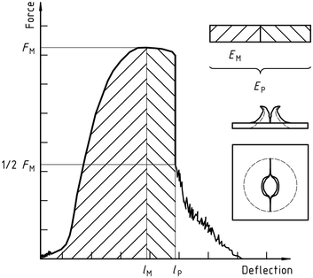
Figure 3 – Example force-deflection diagram of failure through yield (zero slope at maximum force) and the typical appearance (lubrication) of the specimen after testing
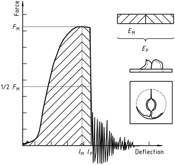
Note the natural vibration of the force detector can be seen after the unstable cracking (firing pin and weighing sensor).
Figure 4 – Example force-deflection diagram of unyielding failure followed by unstable crack propagation and typical appearance of the specimen after testing (using lubrication)
ИСО 6603-2-2000 “Пластика – Determination of puncture impact behaviour of rigid plastics – Парт 2: Instrument impact test”
Јаван је само одељак са стандардним информацијама. Да бисте видели цео садржај, морате купити стандард преко званичних канала.