
ISO 6603-2-2000 “Визначення поведінки при ударі проколу твердих пластмас – частина 2: Випробування приладу на удар”
передмова
ISO (Міжнародна організація стандартизації) є глобальним альянсом національних органів стандартизації (Органи-члени ISO). Розробка міжнародних стандартів зазвичай здійснюється через технічні комітети ISO. Кожна установа-член, зацікавлена в темі, з якої було створено технічний комітет, має право бути представленою в цьому комітеті. До цієї роботи також залучені міжнародні урядові та неурядові організації, які співпрацюють з ISO. ISO тісно співпрацює з Міжнародною електротехнічною комісією (IEC) з усіх питань електротехнічного нормування.
Міжнародні стандарти складаються відповідно до правил, наведених у ч 3 Директиви ISO/IEC.
Проекти міжнародних стандартів, прийняті Технічним комітетом, будуть розіслані членським організаціям для голосування. Публікація як міжнародний стандарт потребує схвалення принаймні 75% членських організацій.
Please note that some elements of this section of ISO 6603 Може бути об'єктом патентних прав. ISO не несе відповідальності за ідентифікацію будь-якого або всіх таких патентів.
Міжнародний стандарт ISO 6603-2 був розроблений Технічним комітетом ISO/TC 61, пластмаси, Підкомітет SC 2, Механічні властивості.
Друге видання скасувало і замінювало перше видання (ISO 6603-2:1989), which had been technically revised.
ISO 6603 consists of the following parts under the general heading Plastics – Визначення ударної поведінки твердої пластмаси на прокол:
— частина 1: Неінструментальні ударні випробування
— частина 2: Instrumental impact testing
The appendices A to E of this part of ISO 6603 are for reference only.
ISO 6603-2-2000 “Визначення поведінки при ударі проколу твердих пластмас – частина 2: Випробування приладу на удар”
1 діапазон
Ця частина ISO 6603 specifies a test method for determining puncture impact properties of rigid plastics in the form of flat specimens using instruments that measure force and deflection. Applies if a force-deflection or force-time plot recorded at a nominal constant firing pin speed is necessary to characterize impact behavior in detail.
If ISO 6603-1 is sufficient to characterize the impact behavior of plastics by impact failure energy thresholds based on many samples, ISO 6603-1 May be used.
Ця частина ISO 6603 is not intended to explain the mechanisms that occur at each particular point in the force-deflection diagram. These explanations are the task of scientific research.
Note also article 1 of ISO 6603-1:2000.
ISO 6603-2-2000 “Визначення поведінки при ударі проколу твердих пластмас – частина 2: Випробування приладу на удар”
2 Нормативні посилання
The following normative documents contain provisions which, за допомогою посилання тут, складають положення цієї частини ISO 6603. Для датованих посилань, жодні подальші перегляди чи поправки до цих публікацій не застосовуватимуться. Проте, Parties to an agreement based on this part of ISO 6603 are encouraged to investigate the possibility of applying the latest version of the following normative documents. Для недатованих посилань, the latest version of the normative document referred to applies. Члени ISO та IEC ведуть реєстр чинних міжнародних стандартів.
ISO 2602:1980, Statistical interpretation of test results – mean Estimators – confidence intervals.
ISO 6603-1:2000, пластмаси. Determination of puncture impact behavior of rigid plastics. частина 1: Non-instrumental impact tests.
3 Терміни та визначення
Для цілей цієї частини ISO 6603, застосовуються наступні терміни та визначення.
3.1 Impact velocity
The speed of the firing pin relative to the support at impact
Примітка 1: The impact velocity is expressed in meters per second (РС).
3.2 Force F
The force exerted by the firing pin on the specimen in the direction of impact
Примітка 1: Force is expressed in Newtons (Н).
3.3 Deflection l
The relative displacement between the firing pin and the specimen support starts from the first contact between the firing pin and the specimen
Примітка 1: Deflection is expressed in millimeters (мм).
3.4 Energy
Energy used to deform and penetrate the specimen up to the deflection L
Примітка 1: Energy is expressed in joules (Дж).
Примітка 2 The energy is measured as the integral of the force-deflection curve from the point of impact to the deflection l.
ISO 6603-2-2000 “Визначення поведінки при ударі проколу твердих пластмас – частина 2: Випробування приладу на удар”
3.5 Maximum power FM
The most power that occurs during the test
Примітка 1: The maximum force is expressed in Newtons (Н).
3.6 Deflection lm at maximum force
Deflection at maximum force FM
Примітка 1 Deflection at maximum force is expressed in millimeters (мм).
3.7 Energy to maximum strength
The energy expended at maximum force reaches deflection lM
Примітка 1: The most powerful energy is expressed in joules (Дж).
3.8 Puncture deflection lP
The force is reduced to half the deflection of the maximum force F M
See Figures 1-4 і 3.9 notes.
Примітка 1 Puncture deflection is expressed in millimeters (мм).
3.9 Puncture energy
Energy expended until the puncture deflects lP
See Figures 1 through 4 and note 2.
Примітка 1: Puncture energy is expressed in joules (Дж).
Примітка 2 A probe mounted at a distance from the impact tip records the friction force acting between the cylindrical part of the firing pin and the piercing material when testing hard materials. The corresponding friction energy should not be included in the piercing energy, so the piercing energy is limited to that deflection, where the force drops to half of the maximum force FM.
ISO 6603-2-2000 “Визначення поведінки при ударі проколу твердих пластмас – частина 2: Випробування приладу на удар”
3.10 Impact Failure
Mechanical properties of the material to be measured, which may be of one of the following types (see note) :
a) YD yIELDING (zero slope at maximum power), then DEEP yielding
b) YS yIELDING (Zero slope at maximum power) Потім (at least partially) cracked the S bench
в) yIELDING of Yu (zero slope at maximum power) Then u unstable cracking
d) no yielding for new features
Примітка 1: A comparison of Figures 2 і 3 shows that puncture deflections l, P and puncture energy EP are the same for failure types YS and YU. As shown in Figure 4, in the case of failure type YU, the deflection and energy values are the same at maximum and puncture. For complex behaviour, дивіться додаток A.
малюнок 1 — An example of a force-deflection diagram of the typical appearance of a specimen after deep drawing and testing (using lubrication) through yield (zero slope at maximum force)
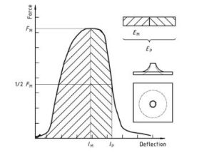
пластмаси – Визначення ударної поведінки твердої пластмаси на прокол – частина 2: Instrument impact test Diagram 1
малюнок 2 — Example force-deflection plot of failure by yield (zero slope at maximum force), followed by steady crack growth, and typical appearance of the specimen after testing (using lubrication)
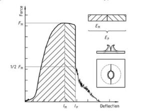
пластмаси – Визначення ударної поведінки твердої пластмаси на прокол – частина 2: Instrument impact test diagram 2
малюнок 3 — Examples of force-deflection plots through yield (zero slope at maximum force) and typical appearance (lubrication) failure of a tested specimen
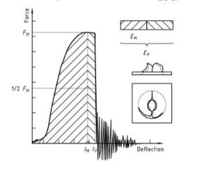
пластмаси – Визначення ударної поведінки твердої пластмаси на прокол – частина 2: Instrument impact test diagram 3
Note that the natural vibration of the force detector can be seen after the unstable cracking (firing pin and weighing sensor).
малюнок 4 — An example force-deflection diagram of an unyielding failure followed by unstable crack growth and a typical appearance of the specimen after testing (using lubrication)
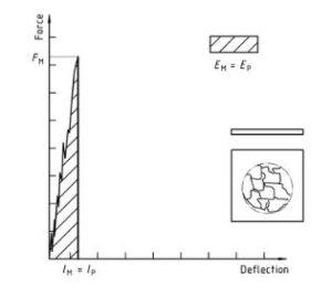
пластмаси – Визначення ударної поведінки твердої пластмаси на прокол – частина 2: Instrument impact test diagram 4
Відкритим є лише стандартний інформаційний розділ. Щоб переглянути повний вміст, необхідно придбати стандарт через офіційні канали.