
ISO 6603-2-2000 “Plasty – Determination of puncture impact behaviour of rigid plastics – Část 2: Instrument impact test”
úvod
ISO (Mezinárodní organizace pro normalizaci) je globální aliance národních normalizačních orgánů (členy ISO). Vývoj mezinárodních norem se obvykle provádí prostřednictvím technických komisí ISO. Každá členská instituce, která se zajímá o předmět, pro který byla ustavena technická komise, má právo být v této komisi zastoupena. Do této práce jsou zapojeny také mezinárodní vládní a nevládní organizace, které jsou ve spojení s ISO. ISO úzce spolupracuje s Mezinárodní elektrotechnickou komisí (IEC) ve všech záležitostech elektrické normalizace.
Mezinárodní normy jsou navrhovány v souladu s pravidly uvedenými v Části 3 směrnice ISO/IEC.
Návrh mezinárodní normy přijatý Technickou komisí bude rozeslán členským orgánům k hlasování. Publikace jako mezinárodní norma vyžaduje schválení min 75% členských institucí.
Please note that some elements of this part of ISO 6603 Může být předmětem patentového práva. ISO nenese odpovědnost za identifikaci některého nebo všech takových patentů.
Mezinárodní standard ISO 6603-2 byl vyvinut technickou komisí ISO/TC 61, Plasty, Podvýbor SC 2, Mechanical Properties.
ISO 6603-2-2000 “Plasty – Determination of puncture impact behaviour of rigid plastics – Část 2: Instrument impact test”
Druhé vydání ruší a nahrazuje první vydání (ISO 6603-2:1989), který byl technicky revidován.
ISO 6603 se skládá z následujících částí, under the general heading Plastics – Determination of puncture impact behaviour of rigid plastics:
– Část 1: Non-instrumental impact testing
– Část 2: Instrumented impact testing
Appendices A to E of this part of ISO 6603 are for information purposes only.
1 Rozsah
Tato část ISO 6603 specifies a test method for determining the puncture impact properties of rigid plastics in the form of flat specimens using instruments that measure force and deflection. This applies if a force-deflection or force-time plot recorded at a nominal constant firing pin speed is necessary to characterize impact behavior in detail.
ISO 6603-1 can be used if ISO 6603-1 is sufficient to characterize the impact behavior of plastics by an impact failure energy threshold based on many samples.
The purpose of this part of ISO 6603 is not to explain the mechanisms that occur at each particular point on the force-deflection chart. These explanations are the task of scientific research.
Note also Article 1 of ISO 6603-1:2000.
ISO 6603-2-2000 “Plasty – Determination of puncture impact behaviour of rigid plastics – Část 2: Instrument impact test”
2 Normativní odkazy
Následující normativní dokumenty obsahují ustanovení, která, odkazem zde, tvoří ustanovení této části ISO 6603. Pro datované odkazy, jakékoli následné revize nebo doplňky těchto publikací nebudou platit. nicméně, Parties to agreements based on this part of ISO 6603 vyzýváme k prozkoumání možnosti použití nových verzí následujících normativních dokumentů. Pro nedatované reference, platí nová verze uvedeného dokumentu o stanovování norem. Členové ISO a IEC vedou registr aktuálně platných mezinárodních norem.
ISO 2602:1980, Statistical interpretation of test results – mean estimation – confidence intervals.
ISO 6603-1:2000, Plasty. Determination of puncture impact behavior of rigid plastics. Část 1: Non-instrumental impact tests.
3 termíny a definice
Pro tuto část ISO 6603, platí následující termíny a definice.
3.1 Impact velocity
The speed of the firing pin relative to the support at the time of impact
Poznámka 1: The impact velocity is expressed in meters per second (slečna).
3.2 Force F
The force exerted by the firing pin on the specimen in the direction of impact
Poznámka 1: Force is expressed in Newtons (N).
3.3 Deflection l
The relative displacement between the firing pin and the specimen holder begins with the first contact between the firing pin and the specimen
Poznámka 1: Deflection is expressed in millimeters (mm).
3.4 Energy
The energy expended to deform and penetrate the specimen up to the deflection L
ISO 6603-2-2000 “Plasty – Determination of puncture impact behaviour of rigid plastics – Část 2: Instrument impact test”
Poznámka 1: Energy is expressed in joules (J).
Poznámka 2: The energy is measured as the integral of the force-deflection curve from the point of impact to the deflection l.
3.5 Maximum Power FM
The test process occurs with maximum force
Poznámka 1: Maximum force is expressed in Newtons (N).
3.6 Deflection lm at maximum force
Deflection at maximum power FM
Poznámka 1: Deflection under maximum force is expressed in millimetres (mm).
3.7 Energy to maximum power
The energy expended at maximum force reaches deflection lM
Poznámka 1: The most powerful energy is expressed in joules (J).
3.8 Puncture deflection lP
The force is reduced to half the deflection of the maximum force F M
See Figures 1-4 and Note 3.9.
Poznámka 1: Puncture deflection is expressed in millimeters (mm).
ISO 6603-2-2000 “Plasty – Determination of puncture impact behaviour of rigid plastics – Část 2: Instrument impact test”
3.9 Puncture Energy
The energy consumed until the puncture deflects lP
See Figures 1-4 and note 2.
Poznámka 1: The puncture energy is expressed in joules (J).
Poznámka 2: When testing hard materials, a probe mounted at a distance from the impact tip can record the friction force acting between the cylindrical part of the firing needle and the piercing material. The corresponding friction energy should not be included in the piercing energy, so the piercing energy is limited to that deflection, where the force drops to half of the maximum force FM.
3.10 Impact Failure
The mechanical properties of the material to be measured may be of one of the following types (see note) :
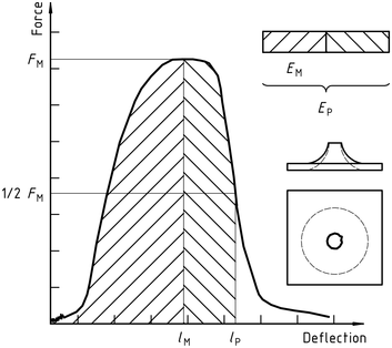
| A) | YD | yIELDING(Zero slope at maximum force), followed by DEEP drawing |
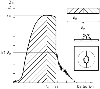
| b) | YS | (Zero slope at maximum force) then (at least partially) the S table cracks |
| C) | yu | yIELDING(Zero slope at maximum force) and then u unstable cracking |
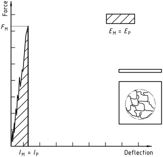
| d) | New function | no yielding |
ISO 6603-2-2000 “Plasty – Determination of puncture impact behaviour of rigid plastics – Část 2: Instrument impact test”
Poznámka 1: A comparison of Figures 2 a 3 shows that puncture deflection lP and puncture energy EP are the same for failure types YS and YU. As shown in Figure 4, in the case of failure type YU, the deflection and energy have the same values at the maximum and at the puncture. For complex behaviour, see annex A.
Postava 1 – An example of a force-deflection diagram of the typical appearance of a specimen after yielding (zero slope at maximum force) followed by deep drawing and testing (using lubrication)
Postava 2 – Example force-deflection diagram of failure by yield (zero slope at maximum force), followed by steady crack growth, and typical appearance of the specimen after testing (using lubrication)
Postava 3 – Example force-deflection diagram of failure through yield (zero slope at maximum force) and the typical appearance (lubrication) of the specimen after testing
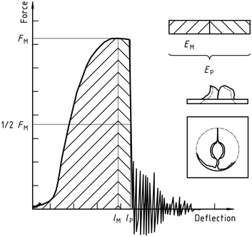
Note the natural vibration of the force detector can be seen after the unstable cracking (firing pin and weighing sensor).
Postava 4 – Example force-deflection diagram of unyielding failure followed by unstable crack propagation and typical appearance of the specimen after testing (using lubrication)
ISO 6603-2-2000 “Plasty – Determination of puncture impact behaviour of rigid plastics – Část 2: Instrument impact test”
Veřejná je pouze standardní informační sekce. Chcete-li zobrazit celý obsah, musíte si standard zakoupit prostřednictvím oficiálních kanálů.