
ISO 6603-2-2000 “Kunststoffe – Bestimmung des Durchstoßverhaltens von Hartkunststoffen – Teil 2: Instrumentenschlagtest”
Einführung
ISO (Internationale Standardisierungsorganisation) ist eine globale Allianz nationaler Normungsgremien (ISO-Mitgliedsorganisationen). Die Entwicklung internationaler Standards erfolgt in der Regel durch technische Komitees der ISO. Jede Mitgliedsinstitution, die an einem Thema interessiert ist, zu dem ein Fachausschuss eingerichtet wurde, hat das Recht, in diesem Ausschuss vertreten zu sein. An dieser Arbeit sind auch internationale Regierungs- und Nichtregierungsorganisationen beteiligt, die mit der ISO zusammenarbeiten. ISO arbeitet eng mit der International Electrotechnical Commission zusammen (IEC) in allen Fragen der elektrischen Normung.
Internationale Normen werden in Übereinstimmung mit den Regeln in Teil erstellt 3 der ISO/IEC-Richtlinie.
Der vom Technischen Komitee angenommene Entwurf einer internationalen Norm wird den Mitgliedsgremien zur Abstimmung vorgelegt. Die Veröffentlichung als internationaler Standard bedarf der Zustimmung von mindestens 75% der Mitgliedsinstitutionen.
Please note that some elements of this part of ISO 6603 Kann Gegenstand eines Patentrechts sein. ISO ist nicht dafür verantwortlich, einige oder alle dieser Patente zu identifizieren.
Der internationale Standard ISO 6603-2 wurde vom Technischen Komitee ISO/TC entwickelt 61, Kunststoffe, Unterausschuss SC 2, Mechanical Properties.
ISO 6603-2-2000 “Kunststoffe – Bestimmung des Durchstoßverhaltens von Hartkunststoffen – Teil 2: Instrumentenschlagtest”
The second edition cancels and replaces the first edition (ISO 6603-2:1989), which has been technically revised.
ISO 6603 besteht aus folgenden Teilen, under the general heading Plastics – Bestimmung des Durchstoßverhaltens von Hartkunststoffen:
– Teil 1: Nicht-instrumentelle Aufprallprüfung
– Teil 2: Instrumented impact testing
Appendices A to E of this part of ISO 6603 are for information purposes only.
1 Reichweite
Dieser Teil von ISO 6603 specifies a test method for determining the puncture impact properties of rigid plastics in the form of flat specimens using instruments that measure force and deflection. This applies if a force-deflection or force-time plot recorded at a nominal constant firing pin speed is necessary to characterize impact behavior in detail.
ISO 6603-1 can be used if ISO 6603-1 is sufficient to characterize the impact behavior of plastics by an impact failure energy threshold based on many samples.
The purpose of this part of ISO 6603 is not to explain the mechanisms that occur at each particular point on the force-deflection chart. These explanations are the task of scientific research.
Note also Article 1 of ISO 6603-1:2000.
ISO 6603-2-2000 “Kunststoffe – Bestimmung des Durchstoßverhaltens von Hartkunststoffen – Teil 2: Instrumentenschlagtest”
2 Normative Verweisungen
The following normative documents contain provisions that, by reference herein, constitute the provisions of this part of ISO 6603. Für datierte Referenzen, any subsequent revisions or amendments to these publications will not apply. Jedoch, Parties to agreements based on this part of ISO 6603 werden ermutigt, die Möglichkeit der Anwendung neuer Versionen der folgenden normativen Dokumente zu prüfen. Für undatierte Referenzen, a new version of the standard-setting document referred to applies. ISO- und IEC-Mitglieder führen ein Register der aktuell gültigen internationalen Standards.
ISO 2602:1980, Statistical interpretation of test results – mean estimation – confidence intervals.
ISO 6603-1:2000, Kunststoffe. Determination of puncture impact behavior of rigid plastics. Teil 1: Non-instrumental impact tests.
3 Begriffe und Definitionen
For this part of ISO 6603, Es gelten die folgenden Begriffe und Definitionen.
3.1 Impact velocity
The speed of the firing pin relative to the support at the time of impact
Notiz 1: The impact velocity is expressed in meters per second (MS).
3.2 Force F
The force exerted by the firing pin on the specimen in the direction of impact
Notiz 1: Force is expressed in Newtons (N).
3.3 Deflection l
The relative displacement between the firing pin and the specimen holder begins with the first contact between the firing pin and the specimen
Notiz 1: Deflection is expressed in millimeters (mm).
3.4 Energy
The energy expended to deform and penetrate the specimen up to the deflection L
ISO 6603-2-2000 “Kunststoffe – Bestimmung des Durchstoßverhaltens von Hartkunststoffen – Teil 2: Instrumentenschlagtest”
Notiz 1: Energy is expressed in joules (J).
Notiz 2: The energy is measured as the integral of the force-deflection curve from the point of impact to the deflection l.
3.5 Maximum Power FM
The test process occurs with maximum force
Notiz 1: Maximum force is expressed in Newtons (N).
3.6 Deflection lm at maximum force
Deflection at maximum power FM
Notiz 1: Deflection under maximum force is expressed in millimetres (mm).
3.7 Energy to maximum power
The energy expended at maximum force reaches deflection lM
Notiz 1: The most powerful energy is expressed in joules (J).
3.8 Puncture deflection lP
The force is reduced to half the deflection of the maximum force F M
See Figures 1-4 and Note 3.9.
Notiz 1: Puncture deflection is expressed in millimeters (mm).
ISO 6603-2-2000 “Kunststoffe – Bestimmung des Durchstoßverhaltens von Hartkunststoffen – Teil 2: Instrumentenschlagtest”
3.9 Puncture Energy
The energy consumed until the puncture deflects lP
See Figures 1-4 and note 2.
Notiz 1: The puncture energy is expressed in joules (J).
Notiz 2: When testing hard materials, a probe mounted at a distance from the impact tip can record the friction force acting between the cylindrical part of the firing needle and the piercing material. The corresponding friction energy should not be included in the piercing energy, so the piercing energy is limited to that deflection, where the force drops to half of the maximum force FM.
3.10 Impact Failure
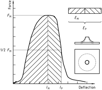
The mechanical properties of the material to be measured may be of one of the following types (see note) :
| A) | YD | yIELDING(Zero slope at maximum force), followed by DEEP drawing |
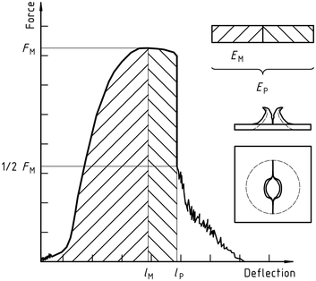
| B) | YS | (Zero slope at maximum force) then (at least partially) the S table cracks |
| C) | yu | yIELDING(Zero slope at maximum force) and then u unstable cracking |
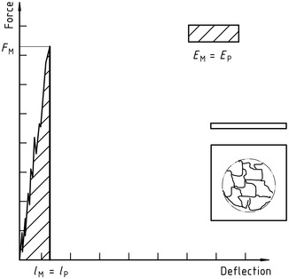
| D) | New function | no yielding |
ISO 6603-2-2000 “Kunststoffe – Bestimmung des Durchstoßverhaltens von Hartkunststoffen – Teil 2: Instrumentenschlagtest”
Notiz 1: A comparison of Figures 2 Und 3 shows that puncture deflection lP and puncture energy EP are the same for failure types YS and YU. As shown in Figure 4, in the case of failure type YU, the deflection and energy have the same values at the maximum and at the puncture. For complex behaviour, see annex A.
Figur 1 – An example of a force-deflection diagram of the typical appearance of a specimen after yielding (zero slope at maximum force) followed by deep drawing and testing (using lubrication)
Figur 2 – Example force-deflection diagram of failure by yield (zero slope at maximum force), followed by steady crack growth, and typical appearance of the specimen after testing (using lubrication)
Figur 3 – Example force-deflection diagram of failure through yield (zero slope at maximum force) and the typical appearance (lubrication) of the specimen after testing
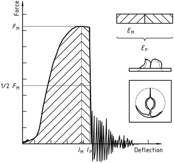
Note the natural vibration of the force detector can be seen after the unstable cracking (firing pin and weighing sensor).
Figur 4 – Example force-deflection diagram of unyielding failure followed by unstable crack propagation and typical appearance of the specimen after testing (using lubrication)
ISO 6603-2-2000 “Kunststoffe – Bestimmung des Durchstoßverhaltens von Hartkunststoffen – Teil 2: Instrumentenschlagtest”
Nur der Standardinformationsbereich ist öffentlich. Um den vollständigen Inhalt zu sehen, Sie müssen den Standard über die offiziellen Kanäle erwerben.