
ISO 6603-2-2000 “Plastica – Determinazione del comportamento all'impatto con foratura di plastiche rigide – Parte 2: Prova di impatto dello strumento”
introduzione
ISO (Organizzazione internazionale per la standardizzazione) è un'alleanza globale di organismi di normalizzazione nazionali (Organismi membri dell'ISO). Lo sviluppo di standard internazionali viene solitamente effettuato attraverso i comitati tecnici ISO. Ciascuna istituzione associata interessata ad una materia sulla quale è stato costituito un comitato tecnico ha il diritto di essere rappresentata in tale comitato. In questo lavoro sono coinvolte anche organizzazioni internazionali governative e non governative che collaborano con l'ISO. L'ISO lavora a stretto contatto con la Commissione Elettrotecnica Internazionale (CEI) su tutte le questioni di standardizzazione elettrica.
Le norme internazionali sono redatte in conformità alle regole riportate nella Part 3 della Direttiva ISO/IEC.
La bozza di norma internazionale adottata dal Comitato Tecnico sarà distribuita agli organi membri per la votazione. La pubblicazione come standard internazionale richiede l'approvazione di almeno 75% delle istituzioni membri.
Si prega di notare che alcuni elementi di questa parte dell'ISO 6603 Può essere oggetto di un diritto di brevetto. L'ISO non è responsabile dell'identificazione di alcuni o tutti questi brevetti.
Lo standard internazionale ISO 6603-2 è stato sviluppato dal Comitato Tecnico ISO/TC 61, Plastica, Sottocommissione SC 2, Proprietà meccaniche.
ISO 6603-2-2000 “Plastica – Determinazione del comportamento all'impatto con foratura di plastiche rigide – Parte 2: Prova di impatto dello strumento”
La seconda edizione annulla e sostituisce la prima edizione (ISO 6603-2:1989), che è stato tecnicamente rivisto.
ISO 6603 è composto dalle seguenti parti, sotto la voce generale Materie plastiche – Determinazione del comportamento all'impatto con foratura di plastiche rigide:
– Parte 1: Prove di impatto non strumentale
– Parte 2: Prove di impatto strumentate
Appendices A to E of this part of ISO 6603 are for information purposes only.
1 Allineare
Questa parte dell'ISO 6603 specifies a test method for determining the puncture impact properties of rigid plastics in the form of flat specimens using instruments that measure force and deflection. This applies if a force-deflection or force-time plot recorded at a nominal constant firing pin speed is necessary to characterize impact behavior in detail.
ISO 6603-1 can be used if ISO 6603-1 is sufficient to characterize the impact behavior of plastics by an impact failure energy threshold based on many samples.
The purpose of this part of ISO 6603 is not to explain the mechanisms that occur at each particular point on the force-deflection chart. These explanations are the task of scientific research.
Note also Article 1 dell'ISO 6603-1:2000.
ISO 6603-2-2000 “Plastica – Determinazione del comportamento all'impatto con foratura di plastiche rigide – Parte 2: Prova di impatto dello strumento”
2 referenze normative
I seguenti documenti normativi contengono disposizioni che, per riferimento qui, costituiscono le disposizioni di questa parte della ISO 6603. Per riferimenti datati, eventuali revisioni o modifiche successive a tali pubblicazioni non troveranno applicazione. Tuttavia, Parti di accordi basati su questa parte dell'ISO 6603 sono incoraggiati ad investigare la possibilità di applicare nuove versioni dei seguenti documenti normativi. Per riferimenti non datati, si applica una nuova versione del documento normativo richiamato. I membri ISO e IEC mantengono un registro degli standard internazionali attualmente validi.
ISO 2602:1980, Statistical interpretation of test results – mean estimation – confidence intervals.
ISO 6603-1:2000, Plastica. Determination of puncture impact behavior of rigid plastics. Parte 1: Non-instrumental impact tests.
3 Termini e definizioni
For this part of ISO 6603, si applicano i seguenti termini e definizioni.
3.1 Velocità d'impatto
The speed of the firing pin relative to the support at the time of impact
Nota 1: The impact velocity is expressed in meters per second (SM).
3.2 Force F
The force exerted by the firing pin on the specimen in the direction of impact
Nota 1: Force is expressed in Newtons (N).
3.3 Deflection l
The relative displacement between the firing pin and the specimen holder begins with the first contact between the firing pin and the specimen
Nota 1: Deflection is expressed in millimeters (mm).
3.4 Energy
The energy expended to deform and penetrate the specimen up to the deflection L
ISO 6603-2-2000 “Plastica – Determinazione del comportamento all'impatto con foratura di plastiche rigide – Parte 2: Prova di impatto dello strumento”
Nota 1: Energy is expressed in joules (J).
Nota 2: The energy is measured as the integral of the force-deflection curve from the point of impact to the deflection l.
3.5 Maximum Power FM
The test process occurs with maximum force
Nota 1: Maximum force is expressed in Newtons (N).
3.6 Deflection lm at maximum force
Deflection at maximum power FM
Nota 1: Deflection under maximum force is expressed in millimetres (mm).
3.7 Energy to maximum power
The energy expended at maximum force reaches deflection lM
Nota 1: The most powerful energy is expressed in joules (J).
3.8 Puncture deflection lP
The force is reduced to half the deflection of the maximum force F M
See Figures 1-4 and Note 3.9.
Nota 1: Puncture deflection is expressed in millimeters (mm).
ISO 6603-2-2000 “Plastica – Determinazione del comportamento all'impatto con foratura di plastiche rigide – Parte 2: Prova di impatto dello strumento”
3.9 Puncture Energy
The energy consumed until the puncture deflects lP
See Figures 1-4 and note 2.
Nota 1: The puncture energy is expressed in joules (J).
Nota 2: When testing hard materials, a probe mounted at a distance from the impact tip can record the friction force acting between the cylindrical part of the firing needle and the piercing material. The corresponding friction energy should not be included in the piercing energy, so the piercing energy is limited to that deflection, where the force drops to half of the maximum force FM.
3.10 Impact Failure
The mechanical properties of the material to be measured may be of one of the following types (see note) :
| UN) | YD | yIELDING(Zero slope at maximum force), followed by DEEP drawing |
| B) | YS | (Zero slope at maximum force) Poi (at least partially) the S table cracks |
| C) | yu | yIELDING(Zero slope at maximum force) and then u unstable cracking |
| D) | New function | no yielding |
ISO 6603-2-2000 “Plastica – Determinazione del comportamento all'impatto con foratura di plastiche rigide – Parte 2: Prova di impatto dello strumento”
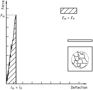
Nota 1: A comparison of Figures 2 E 3 shows that puncture deflection lP and puncture energy EP are the same for failure types YS and YU. As shown in Figure 4, in the case of failure type YU, the deflection and energy have the same values at the maximum and at the puncture. For complex behaviour, see annex A.
Figura 1 – An example of a force-deflection diagram of the typical appearance of a specimen after yielding (zero slope at maximum force) followed by deep drawing and testing (using lubrication)
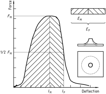
Figura 2 – Example force-deflection diagram of failure by yield (zero slope at maximum force), followed by steady crack growth, and typical appearance of the specimen after testing (using lubrication)
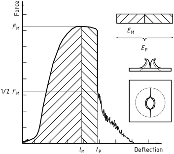
Figura 3 – Example force-deflection diagram of failure through yield (zero slope at maximum force) and the typical appearance (lubrication) of the specimen after testing
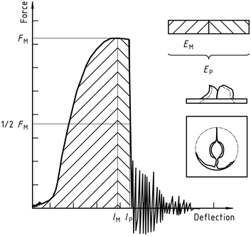
Note the natural vibration of the force detector can be seen after the unstable cracking (firing pin and weighing sensor).
Figura 4 – Example force-deflection diagram of unyielding failure followed by unstable crack propagation and typical appearance of the specimen after testing (using lubrication)
ISO 6603-2-2000 “Plastica – Determinazione del comportamento all'impatto con foratura di plastiche rigide – Parte 2: Prova di impatto dello strumento”
Solo la sezione informativa standard è pubblica. Per vedere il contenuto completo, è necessario acquistare lo standard attraverso i canali ufficiali.