
ISO 6603-2-2000 “Determinação do comportamento de impacto de punção de plásticos duros – Papel 2: Teste de impacto do instrumento”
prefácio
ISO (Organização Internacional para Padronização) é uma aliança global de organismos nacionais de normalização (Órgãos membros da ISO). O desenvolvimento de padrões internacionais é geralmente realizado através de comitês técnicos ISO. Cada instituição membro interessada em um assunto sobre o qual tenha sido estabelecido um comitê técnico tem o direito de ser representada nesse comitê. Organizações internacionais governamentais e não governamentais em ligação com a ISO também estão envolvidas neste trabalho. A ISO trabalha em estreita colaboração com a Comissão Eletrotécnica Internacional (CEI) em todos os assuntos de padronização eletrotécnica.
As normas internacionais são elaboradas de acordo com as regras fornecidas na Parte 3 da Diretiva ISO/IEC.
Os projetos de normas internacionais adotados pelo Comitê Técnico serão distribuídos aos órgãos membros para votação. A publicação como padrão internacional requer aprovação de pelo menos 75% dos órgãos membros.
Please note that some elements of this section of ISO 6603 May be the subject of patent rights. A ISO não é responsável por identificar nenhuma ou todas essas patentes.
Padrão internacional ISO 6603-2 foi desenvolvido pelo Comitê Técnico ISO/TC 61, Plásticos, Subcomitê SC 2, Mechanical Properties.
The second edition cancelled and replaced the first edition (ISO 6603-2:1989), which had been technically revised.
ISO 6603 consists of the following parts under the general heading Plastics – Determinação do comportamento de impacto de punção de plásticos rígidos:
— Papel 1: Testes de impacto não instrumentais
— Papel 2: Instrumental impact testing
The appendices A to E of this part of ISO 6603 are for reference only.
ISO 6603-2-2000 “Determinação do comportamento de impacto de punção de plásticos duros – Papel 2: Teste de impacto do instrumento”
1 faixa
Esta parte da ISO 6603 specifies a test method for determining puncture impact properties of rigid plastics in the form of flat specimens using instruments that measure force and deflection. Applies if a force-deflection or force-time plot recorded at a nominal constant firing pin speed is necessary to characterize impact behavior in detail.
If ISO 6603-1 is sufficient to characterize the impact behavior of plastics by impact failure energy thresholds based on many samples, ISO 6603-1 May be used.
Esta parte da ISO 6603 is not intended to explain the mechanisms that occur at each particular point in the force-deflection diagram. These explanations are the task of scientific research.
Note also article 1 of ISO 6603-1:2000.
ISO 6603-2-2000 “Determinação do comportamento de impacto de punção de plásticos duros – Papel 2: Teste de impacto do instrumento”
2 referências normativas
The following normative documents contain provisions which, por referência aqui, constituem as disposições desta parte da ISO 6603. Para referências datadas, no subsequent revisions or amendments to these publications will apply. No entanto, Partes de um acordo baseado nesta parte da ISO 6603 are encouraged to investigate the possibility of applying the latest version of the following normative documents. Para referências sem data, the latest version of the normative document referred to applies. Members of ISO and IEC maintain a register of international standards currently in force.
ISO 2602:1980, Statistical interpretation of test results – mean Estimators – confidence intervals.
ISO 6603-1:2000, Plásticos. Determination of puncture impact behavior of rigid plastics. Papel 1: Non-instrumental impact tests.
3 Termos e definições
For the purposes of this part of ISO 6603, os seguintes termos e definições se aplicam.
3.1 Impact velocity
The speed of the firing pin relative to the support at impact
Observação 1: The impact velocity is expressed in meters per second (EM).
3.2 Force F
The force exerted by the firing pin on the specimen in the direction of impact
Observação 1: Force is expressed in Newtons (N).
3.3 Deflection l
The relative displacement between the firing pin and the specimen support starts from the first contact between the firing pin and the specimen
Observação 1: Deflection is expressed in millimeters (milímetros).
3.4 Energy
Energy used to deform and penetrate the specimen up to the deflection L
Observação 1: Energy is expressed in joules (J.).
Observação 2 The energy is measured as the integral of the force-deflection curve from the point of impact to the deflection l.
ISO 6603-2-2000 “Determinação do comportamento de impacto de punção de plásticos duros – Papel 2: Teste de impacto do instrumento”
3.5 Maximum power FM
The most power that occurs during the test
Observação 1: The maximum force is expressed in Newtons (N).
3.6 Deflection lm at maximum force
Deflection at maximum force FM
Observação 1 Deflection at maximum force is expressed in millimeters (milímetros).
3.7 Energy to maximum strength
The energy expended at maximum force reaches deflection lM
Observação 1: The most powerful energy is expressed in joules (J.).
3.8 Puncture deflection lP
The force is reduced to half the deflection of the maximum force F M
See Figures 1-4 e 3.9 notes.
Observação 1 Puncture deflection is expressed in millimeters (milímetros).
3.9 Puncture energy
Energy expended until the puncture deflects lP
See Figures 1 through 4 and note 2.
Observação 1: Puncture energy is expressed in joules (J.).
Observação 2 A probe mounted at a distance from the impact tip records the friction force acting between the cylindrical part of the firing pin and the piercing material when testing hard materials. The corresponding friction energy should not be included in the piercing energy, so the piercing energy is limited to that deflection, where the force drops to half of the maximum force FM.
ISO 6603-2-2000 “Determinação do comportamento de impacto de punção de plásticos duros – Papel 2: Teste de impacto do instrumento”
3.10 Impact Failure
Mechanical properties of the material to be measured, which may be of one of the following types (Veja a nota) :
a) YD yIELDING (zero slope at maximum power), then DEEP yielding
b) YS yIELDING (Zero slope at maximum power) Então (at least partially) cracked the S bench
c) yIELDING of Yu (zero slope at maximum power) Then u unstable cracking
d) no yielding for new features
Observação 1: A comparison of Figures 2 e 3 shows that puncture deflections l, P and puncture energy EP are the same for failure types YS and YU. As shown in Figure 4, in the case of failure type YU, the deflection and energy values are the same at maximum and puncture. For complex behaviour, ver Anexo A.
Figura 1 — An example of a force-deflection diagram of the typical appearance of a specimen after deep drawing and testing (using lubrication) through yield (zero slope at maximum force)
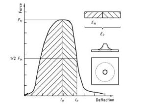
Plásticos – Determinação do comportamento de impacto de punção de plásticos rígidos – Papel 2: Instrument impact test Diagram 1
Figura 2 — Example force-deflection plot of failure by yield (zero slope at maximum force), followed by steady crack growth, and typical appearance of the specimen after testing (using lubrication)
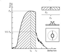
Plásticos – Determinação do comportamento de impacto de punção de plásticos rígidos – Papel 2: Instrument impact test diagram 2
Figura 3 — Examples of force-deflection plots through yield (zero slope at maximum force) and typical appearance (lubrication) failure of a tested specimen
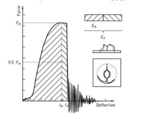
Plásticos – Determinação do comportamento de impacto de punção de plásticos rígidos – Papel 2: Instrument impact test diagram 3
Note that the natural vibration of the force detector can be seen after the unstable cracking (firing pin and weighing sensor).
Figura 4 — An example force-deflection diagram of an unyielding failure followed by unstable crack growth and a typical appearance of the specimen after testing (using lubrication)
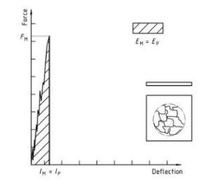
Plásticos – Determinação do comportamento de impacto de punção de plásticos rígidos – Papel 2: Instrument impact test diagram 4
Apenas a seção de informações padrão é pública. Para ver o conteúdo completo, você precisa adquirir o padrão pelos canais oficiais.