
ISO 6603-2-2000 “Plastikler – Sert plastiklerin delinme darbe davranışının belirlenmesi – Parça 2: Enstrüman darbe testi”
giriiş
ISO (Uluslararası Standardizasyon Örgütü) ulusal standart kuruluşlarının küresel bir ittifakıdır (ISO üyesi kuruluşlar). Uluslararası standartların geliştirilmesi genellikle ISO teknik komiteleri aracılığıyla yürütülür.. Teknik komite oluşturulmuş bir konu ile ilgilenen her üye kuruluşun o komitede temsil edilme hakkı vardır.. ISO ile irtibat halinde olan uluslararası resmi ve sivil toplum kuruluşları da bu çalışmaya katılıyor. ISO, Uluslararası Elektroteknik Komisyonu ile yakın işbirliği içinde çalışır. (IEC) elektriksel standardizasyonla ilgili tüm konularda.
Uluslararası standartlar Bölüm 1'de verilen kurallara uygun olarak hazırlanmıştır. 3 ISO/IEC Direktifi.
Teknik Komite tarafından kabul edilen uluslararası standart taslağı oylanmak üzere üye kuruluşlara dağıtılacaktır.. Uluslararası bir standart olarak yayın, en azından onay gerektirir 75% üye kuruluşların.
Please note that some elements of this part of ISO 6603 May be the subject of a patent right. ISO bu tür patentlerin herhangi birinin veya tamamının tanımlanmasından sorumlu değildir..
Uluslararası standart ISO 6603-2 Teknik Komite ISO/TC tarafından geliştirildi 61, Plastikler, Alt Komite SC 2, Mechanical Properties.
ISO 6603-2-2000 “Plastikler – Sert plastiklerin delinme darbe davranışının belirlenmesi – Parça 2: Enstrüman darbe testi”
İkinci baskı, ilk baskıyı iptal eder ve onun yerine geçer (ISO 6603-2:1989), which has been technically revised.
ISO 6603 aşağıdaki parçalardan oluşur, under the general heading Plastics – Sert plastiklerin delinme darbe davranışının belirlenmesi:
– Parça 1: Enstrümantal olmayan darbe testi
– Parça 2: Instrumented impact testing
Appendices A to E of this part of ISO 6603 are for information purposes only.
1 Menzil
ISO'nun bu kısmı 6603 specifies a test method for determining the puncture impact properties of rigid plastics in the form of flat specimens using instruments that measure force and deflection. This applies if a force-deflection or force-time plot recorded at a nominal constant firing pin speed is necessary to characterize impact behavior in detail.
ISO 6603-1 can be used if ISO 6603-1 is sufficient to characterize the impact behavior of plastics by an impact failure energy threshold based on many samples.
The purpose of this part of ISO 6603 is not to explain the mechanisms that occur at each particular point on the force-deflection chart. These explanations are the task of scientific research.
Note also Article 1 of ISO 6603-1:2000.
ISO 6603-2-2000 “Plastikler – Sert plastiklerin delinme darbe davranışının belirlenmesi – Parça 2: Enstrüman darbe testi”
2 Normatif referanslar
The following normative documents contain provisions that, by reference herein, constitute the provisions of this part of ISO 6603. Tarihli referanslar için, any subsequent revisions or amendments to these publications will not apply. Fakat, Parties to agreements based on this part of ISO 6603 are encouraged to investigate the possibility of applying new versions of the following normative documents. Tarihsiz referanslar için, a new version of the standard-setting document referred to applies. ISO and IEC members maintain a register of currently valid international standards.
ISO 2602:1980, Statistical interpretation of test results – mean estimation – confidence intervals.
ISO 6603-1:2000, Plastikler. Determination of puncture impact behavior of rigid plastics. Parça 1: Non-instrumental impact tests.
3 Terimler ve tanımlar
For this part of ISO 6603, aşağıdaki terimler ve tanımlar geçerlidir.
3.1 Impact velocity
The speed of the firing pin relative to the support at the time of impact
Not 1: The impact velocity is expressed in meters per second (Hanım).
3.2 Force F
The force exerted by the firing pin on the specimen in the direction of impact
Not 1: Force is expressed in Newtons (N).
3.3 Deflection l
The relative displacement between the firing pin and the specimen holder begins with the first contact between the firing pin and the specimen
Not 1: Deflection is expressed in millimeters (mm).
3.4 Energy
The energy expended to deform and penetrate the specimen up to the deflection L
ISO 6603-2-2000 “Plastikler – Sert plastiklerin delinme darbe davranışının belirlenmesi – Parça 2: Enstrüman darbe testi”
Not 1: Energy is expressed in joules (J).
Not 2: The energy is measured as the integral of the force-deflection curve from the point of impact to the deflection l.
3.5 Maximum Power FM
The test process occurs with maximum force
Not 1: Maximum force is expressed in Newtons (N).
3.6 Deflection lm at maximum force
Deflection at maximum power FM
Not 1: Deflection under maximum force is expressed in millimetres (mm).
3.7 Energy to maximum power
The energy expended at maximum force reaches deflection lM
Not 1: The most powerful energy is expressed in joules (J).
3.8 Puncture deflection lP
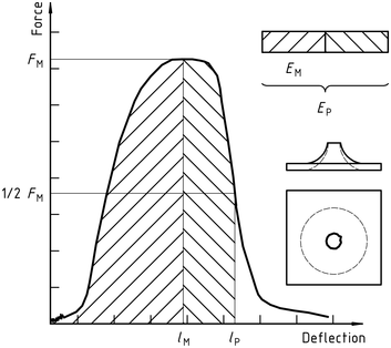
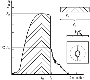
The force is reduced to half the deflection of the maximum force F M
See Figures 1-4 and Note 3.9.
Not 1: Puncture deflection is expressed in millimeters (mm).
ISO 6603-2-2000 “Plastikler – Sert plastiklerin delinme darbe davranışının belirlenmesi – Parça 2: Enstrüman darbe testi”
3.9 Puncture Energy
The energy consumed until the puncture deflects lP
See Figures 1-4 and note 2.
Not 1: The puncture energy is expressed in joules (J).
Not 2: When testing hard materials, a probe mounted at a distance from the impact tip can record the friction force acting between the cylindrical part of the firing needle and the piercing material. The corresponding friction energy should not be included in the piercing energy, so the piercing energy is limited to that deflection, where the force drops to half of the maximum force FM.
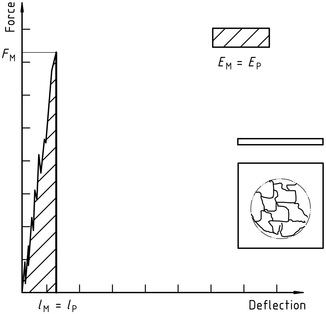
3.10 Impact Failure
The mechanical properties of the material to be measured may be of one of the following types (notu gör) :
| A) | YD | yIELDING(Zero slope at maximum force), followed by DEEP drawing |
| B) | YS | (Zero slope at maximum force) then (at least partially) the S table cracks |
| C) | yu | yIELDING(Zero slope at maximum force) and then u unstable cracking |
| D) | New function | no yielding |
ISO 6603-2-2000 “Plastikler – Sert plastiklerin delinme darbe davranışının belirlenmesi – Parça 2: Enstrüman darbe testi”
Not 1: A comparison of Figures 2 Ve 3 shows that puncture deflection lP and puncture energy EP are the same for failure types YS and YU. As shown in Figure 4, in the case of failure type YU, the deflection and energy have the same values at the maximum and at the puncture. For complex behaviour, see annex A.
Figür 1 – An example of a force-deflection diagram of the typical appearance of a specimen after yielding (zero slope at maximum force) followed by deep drawing and testing (using lubrication)
Figür 2 – Example force-deflection diagram of failure by yield (zero slope at maximum force), followed by steady crack growth, and typical appearance of the specimen after testing (using lubrication)
Figür 3 – Example force-deflection diagram of failure through yield (zero slope at maximum force) and the typical appearance (lubrication) of the specimen after testing
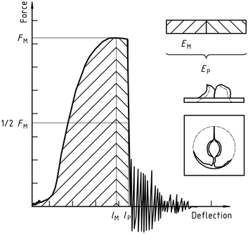
Note the natural vibration of the force detector can be seen after the unstable cracking (firing pin and weighing sensor).
Figür 4 – Example force-deflection diagram of unyielding failure followed by unstable crack propagation and typical appearance of the specimen after testing (using lubrication)
ISO 6603-2-2000 “Plastikler – Sert plastiklerin delinme darbe davranışının belirlenmesi – Parça 2: Enstrüman darbe testi”
Yalnızca standart bilgi bölümü herkese açıktır. İçeriğin tamamını görmek için, standardı resmi kanallardan satın almanız gerekiyor.