
ايزو 6603-2-2000 “البلاستيك البلاستيك الصلب ثقب تحديد سلوك التأثير – جزء 2: اختبار تأثير الأداة”
مقدمة
ايزو (المنظمة الدولية للمقاييس) هو تحالف عالمي لهيئات المعايير الوطنية (الهيئات الأعضاء في منظمة الأيزو). عادة ما يتم تطوير المعايير الدولية من خلال اللجان الفنية ISO. يحق لكل مؤسسة عضو مهتمة بموضوع تم تشكيل لجنة فنية له أن تكون ممثلة في تلك اللجنة. وتشارك أيضًا في هذا العمل المنظمات الحكومية الدولية وغير الحكومية المتعاونة مع ISO. تعمل ISO بشكل وثيق مع اللجنة الكهروتقنية الدولية (اللجنة الانتخابية المستقلة) في جميع المسائل المتعلقة بالتوحيد القياسي الكهروتقني.
تتم صياغة المعايير الدولية وفقًا للقواعد الواردة في الجزء 3 لتوجيهات ISO/IEC.
وسيتم توزيع مشروع المعايير الدولية الذي اعتمدته اللجنة الفنية على الهيئات الأعضاء للتصويت عليه. النشر كمعيار دولي يتطلب موافقة على الأقل 75% of member bodies.
Please note that some elements of this section of ISO 6603 قد يكون موضوع حقوق براءات الاختراع. ISO ليست مسؤولة عن تحديد أي أو كل براءات الاختراع هذه.
المعيار الدولي ISO 6603-2 تم تطويره من قبل اللجنة الفنية ISO/TC 61, البلاستيك, اللجنة الفرعية SC 2, Mechanical Properties.
The second edition cancelled and replaced the first edition (ايزو 6603-2:1989), which had been technically revised.
ايزو 6603 consists of the following parts under the general heading Plastics – تحديد سلوك تأثير ثقب المواد البلاستيكية الصلبة:
— جزء 1: Non-instrumental impact testing
— جزء 2: Instrumental impact testing
The appendices A to E of this part of ISO 6603 are for reference only.
ايزو 6603-2-2000 “البلاستيك البلاستيك الصلب ثقب تحديد سلوك التأثير – جزء 2: اختبار تأثير الأداة”
1 يتراوح
هذا الجزء من ISO 6603 specifies a test method for determining puncture impact properties of rigid plastics in the form of flat specimens using instruments that measure force and deflection. Applies if a force-deflection or force-time plot recorded at a nominal constant firing pin speed is necessary to characterize impact behavior in detail.
If ISO 6603-1 is sufficient to characterize the impact behavior of plastics by impact failure energy thresholds based on many samples, ايزو 6603-1 May be used.
هذا الجزء من ISO 6603 is not intended to explain the mechanisms that occur at each particular point in the force-deflection diagram. These explanations are the task of scientific research.
Note also article 1 of ISO 6603-1:2000.
ايزو 6603-2-2000 “البلاستيك البلاستيك الصلب ثقب تحديد سلوك التأثير – جزء 2: اختبار تأثير الأداة”
2 المراجع المعيارية
The following normative documents contain provisions which, بالإشارة هنا, تشكل أحكام هذا الجزء من ISO 6603. للمراجع المؤرخة, لن يتم تطبيق أي مراجعات أو تعديلات لاحقة على هذه المنشورات. لكن, الأطراف في اتفاقية بناءً على هذا الجزء من ISO 6603 are encouraged to investigate the possibility of applying the latest version of the following normative documents. للمراجع غير المؤرخة, the latest version of the normative document referred to applies. يحتفظ أعضاء ISO وIEC بسجل للمعايير الدولية المعمول بها حاليًا.
ايزو 2602:1980, Statistical interpretation of test results – mean Estimators – confidence intervals.
ايزو 6603-1:2000, البلاستيك. Determination of puncture impact behavior of rigid plastics. جزء 1: Non-instrumental impact tests.
3 المصطلحات والتعاريف
ولأغراض هذا الجزء من ISO 6603, تنطبق المصطلحات والتعاريف التالية.
3.1 Impact velocity
The speed of the firing pin relative to the support at impact
ملحوظة 1: The impact velocity is expressed in meters per second (آنسة).
3.2 Force F
The force exerted by the firing pin on the specimen in the direction of impact
ملحوظة 1: Force is expressed in Newtons (ن).
3.3 Deflection l
The relative displacement between the firing pin and the specimen support starts from the first contact between the firing pin and the specimen
ملحوظة 1: Deflection is expressed in millimeters (مم).
3.4 Energy
Energy used to deform and penetrate the specimen up to the deflection L
ملحوظة 1: Energy is expressed in joules (ج).
ملحوظة 2 The energy is measured as the integral of the force-deflection curve from the point of impact to the deflection l.
ايزو 6603-2-2000 “البلاستيك البلاستيك الصلب ثقب تحديد سلوك التأثير – جزء 2: اختبار تأثير الأداة”
3.5 Maximum power FM
The most power that occurs during the test
ملحوظة 1: The maximum force is expressed in Newtons (ن).
3.6 Deflection lm at maximum force
Deflection at maximum force FM
ملحوظة 1 Deflection at maximum force is expressed in millimeters (مم).
3.7 Energy to maximum strength
The energy expended at maximum force reaches deflection lM
ملحوظة 1: The most powerful energy is expressed in joules (ج).
3.8 Puncture deflection lP
The force is reduced to half the deflection of the maximum force F M
See Figures 1-4 و 3.9 notes.
ملحوظة 1 Puncture deflection is expressed in millimeters (مم).
3.9 Puncture energy
Energy expended until the puncture deflects lP
See Figures 1 خلال 4 and note 2.
ملحوظة 1: Puncture energy is expressed in joules (ج).
ملحوظة 2 A probe mounted at a distance from the impact tip records the friction force acting between the cylindrical part of the firing pin and the piercing material when testing hard materials. The corresponding friction energy should not be included in the piercing energy, so the piercing energy is limited to that deflection, where the force drops to half of the maximum force FM.
ايزو 6603-2-2000 “البلاستيك البلاستيك الصلب ثقب تحديد سلوك التأثير – جزء 2: اختبار تأثير الأداة”
3.10 Impact Failure
Mechanical properties of the material to be measured, which may be of one of the following types (انظر الملاحظة) :
أ) YD yIELDING (zero slope at maximum power), then DEEP yielding
ب) YS yIELDING (Zero slope at maximum power) ثم (at least partially) cracked the S bench
ج) yIELDING of Yu (zero slope at maximum power) Then u unstable cracking
د) no yielding for new features
ملحوظة 1: A comparison of Figures 2 و 3 shows that puncture deflections l, P and puncture energy EP are the same for failure types YS and YU. As shown in Figure 4, in the case of failure type YU, the deflection and energy values are the same at maximum and puncture. For complex behaviour, انظر الملحق أ.
شكل 1 — An example of a force-deflection diagram of the typical appearance of a specimen after deep drawing and testing (using lubrication) through yield (zero slope at maximum force)
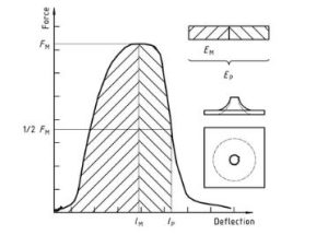
البلاستيك – تحديد سلوك تأثير ثقب المواد البلاستيكية الصلبة – جزء 2: Instrument impact test Diagram 1
شكل 2 — Example force-deflection plot of failure by yield (zero slope at maximum force), followed by steady crack growth, and typical appearance of the specimen after testing (using lubrication)
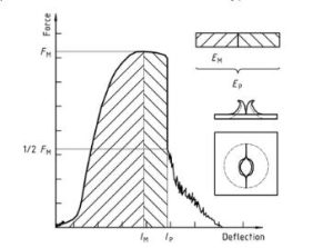
البلاستيك – تحديد سلوك تأثير ثقب المواد البلاستيكية الصلبة – جزء 2: Instrument impact test diagram 2
شكل 3 — Examples of force-deflection plots through yield (zero slope at maximum force) and typical appearance (lubrication) failure of a tested specimen
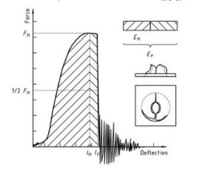
البلاستيك – تحديد سلوك تأثير ثقب المواد البلاستيكية الصلبة – جزء 2: Instrument impact test diagram 3
Note that the natural vibration of the force detector can be seen after the unstable cracking (firing pin and weighing sensor).
شكل 4 — An example force-deflection diagram of an unyielding failure followed by unstable crack growth and a typical appearance of the specimen after testing (using lubrication)
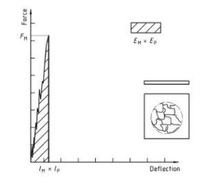
البلاستيك – تحديد سلوك تأثير ثقب المواد البلاستيكية الصلبة – جزء 2: Instrument impact test diagram 4
قسم المعلومات القياسية فقط هو العام. لرؤية المحتوى كاملا, تحتاج إلى شراء المعيار من خلال القنوات الرسمية.