
ISO 6603-2-2000 “Plastik keras, plastik keras, tusukan, berdampak pada penentuan perilaku – Bagian 2: Uji dampak instrumen”
kata pengantar
ISO (Organisasi Internasional untuk Standardisasi) adalah aliansi global badan standar nasional (badan anggota ISO). Pengembangan standar internasional biasanya dilakukan melalui komite teknis ISO. Setiap lembaga anggota yang tertarik pada suatu mata pelajaran yang telah dibentuk komite teknisnya berhak untuk diwakili dalam komite tersebut. Organisasi pemerintah dan non-pemerintah internasional yang bekerja sama dengan ISO juga terlibat dalam pekerjaan ini. ISO bekerja sama dengan Komisi Elektroteknik Internasional (IEC) tentang semua masalah standardisasi elektroteknik.
Standar internasional disusun sesuai dengan aturan yang diberikan di Bagian 3 dari Petunjuk ISO/IEC.
Rancangan standar internasional yang diadopsi oleh Komite Teknis akan diedarkan ke badan-badan anggota untuk pemungutan suara. Publikasi sebagai standar internasional memerlukan persetujuan paling sedikit 75% dari badan anggota.
Please note that some elements of this section of ISO 6603 May be the subject of patent rights. ISO tidak bertanggung jawab untuk mengidentifikasi salah satu atau semua paten tersebut.
ISO standar internasional 6603-2 dikembangkan oleh Komite Teknis ISO/TC 61, Plastik, Subkomite SC 2, Mechanical Properties.
Edisi kedua membatalkan dan menggantikan edisi pertama (ISO 6603-2:1989), yang telah direvisi secara teknis.
ISO 6603 consists of the following parts under the general heading Plastics – Penentuan perilaku dampak tusukan plastik kaku:
— Bagian 1: Pengujian dampak non-instrumental
— Bagian 2: Instrumental impact testing
The appendices A to E of this part of ISO 6603 are for reference only.
ISO 6603-2-2000 “Plastik keras, plastik keras, tusukan, berdampak pada penentuan perilaku – Bagian 2: Uji dampak instrumen”
1 jangkauan
Bagian dari ISO ini 6603 specifies a test method for determining puncture impact properties of rigid plastics in the form of flat specimens using instruments that measure force and deflection. Applies if a force-deflection or force-time plot recorded at a nominal constant firing pin speed is necessary to characterize impact behavior in detail.
If ISO 6603-1 is sufficient to characterize the impact behavior of plastics by impact failure energy thresholds based on many samples, ISO 6603-1 May be used.
Bagian dari ISO ini 6603 is not intended to explain the mechanisms that occur at each particular point in the force-deflection diagram. These explanations are the task of scientific research.
Note also article 1 of ISO 6603-1:2000.
ISO 6603-2-2000 “Plastik keras, plastik keras, tusukan, berdampak pada penentuan perilaku – Bagian 2: Uji dampak instrumen”
2 Acuan normatif
The following normative documents contain provisions which, by reference herein, merupakan ketentuan bagian ISO ini 6603. Untuk referensi bertanggal, no subsequent revisions or amendments to these publications will apply. Namun, Parties to an agreement based on this part of ISO 6603 are encouraged to investigate the possibility of applying the latest version of the following normative documents. Untuk referensi tidak bertanggal, the latest version of the normative document referred to applies. Members of ISO and IEC maintain a register of international standards currently in force.
ISO 2602:1980, Statistical interpretation of test results – mean Estimators – confidence intervals.
ISO 6603-1:2000, Plastik. Determination of puncture impact behavior of rigid plastics. Bagian 1: Non-instrumental impact tests.
3 Istilah dan Definisi
For the purposes of this part of ISO 6603, istilah dan definisi berikut berlaku.
3.1 Kecepatan tumbukan
The speed of the firing pin relative to the support at impact
Catatan 1: The impact velocity is expressed in meters per second (MS).
3.2 Force F
The force exerted by the firing pin on the specimen in the direction of impact
Catatan 1: Force is expressed in Newtons (N).
3.3 Deflection l
The relative displacement between the firing pin and the specimen support starts from the first contact between the firing pin and the specimen
Catatan 1: Deflection is expressed in millimeters (mm).
3.4 Energy
Energy used to deform and penetrate the specimen up to the deflection L
Catatan 1: Energy is expressed in joules (J).
Catatan 2 The energy is measured as the integral of the force-deflection curve from the point of impact to the deflection l.
ISO 6603-2-2000 “Plastik keras, plastik keras, tusukan, berdampak pada penentuan perilaku – Bagian 2: Uji dampak instrumen”
3.5 Maximum power FM
The most power that occurs during the test
Catatan 1: The maximum force is expressed in Newtons (N).
3.6 Deflection lm at maximum force
Deflection at maximum force FM
Catatan 1 Deflection at maximum force is expressed in millimeters (mm).
3.7 Energy to maximum strength
The energy expended at maximum force reaches deflection lM
Catatan 1: The most powerful energy is expressed in joules (J).
3.8 Puncture deflection lP
The force is reduced to half the deflection of the maximum force F M
See Figures 1-4 Dan 3.9 notes.
Catatan 1 Puncture deflection is expressed in millimeters (mm).
3.9 Puncture energy
Energy expended until the puncture deflects lP
See Figures 1 melalui 4 and note 2.
Catatan 1: Puncture energy is expressed in joules (J).
Catatan 2 A probe mounted at a distance from the impact tip records the friction force acting between the cylindrical part of the firing pin and the piercing material when testing hard materials. The corresponding friction energy should not be included in the piercing energy, so the piercing energy is limited to that deflection, where the force drops to half of the maximum force FM.
ISO 6603-2-2000 “Plastik keras, plastik keras, tusukan, berdampak pada penentuan perilaku – Bagian 2: Uji dampak instrumen”
3.10 Impact Failure
Mechanical properties of the material to be measured, which may be of one of the following types (Lihat Catatan) :
A) YD yIELDING (zero slope at maximum power), then DEEP yielding
B) YS yIELDING (Zero slope at maximum power) Kemudian (at least partially) cracked the S bench
C) yIELDING of Yu (zero slope at maximum power) Then u unstable cracking
D) no yielding for new features
Catatan 1: A comparison of Figures 2 Dan 3 shows that puncture deflections l, P and puncture energy EP are the same for failure types YS and YU. As shown in Figure 4, in the case of failure type YU, the deflection and energy values are the same at maximum and puncture. For complex behaviour, see Annex A.
Angka 1 — An example of a force-deflection diagram of the typical appearance of a specimen after deep drawing and testing (using lubrication) through yield (zero slope at maximum force)
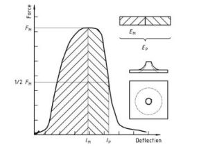
Plastik – Penentuan perilaku dampak tusukan plastik kaku – Bagian 2: Instrument impact test Diagram 1
Angka 2 — Example force-deflection plot of failure by yield (zero slope at maximum force), followed by steady crack growth, and typical appearance of the specimen after testing (using lubrication)
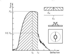
Plastik – Penentuan perilaku dampak tusukan plastik kaku – Bagian 2: Instrument impact test diagram 2
Angka 3 — Examples of force-deflection plots through yield (zero slope at maximum force) and typical appearance (lubrication) failure of a tested specimen
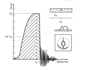
Plastik – Penentuan perilaku dampak tusukan plastik kaku – Bagian 2: Instrument impact test diagram 3
Note that the natural vibration of the force detector can be seen after the unstable cracking (firing pin and weighing sensor).
Angka 4 — An example force-deflection diagram of an unyielding failure followed by unstable crack growth and a typical appearance of the specimen after testing (using lubrication)
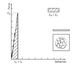
Plastik – Penentuan perilaku dampak tusukan plastik kaku – Bagian 2: Instrument impact test diagram 4
Hanya bagian informasi standar yang bersifat publik. Untuk melihat konten selengkapnya, Anda perlu membeli standar melalui saluran resmi.