
ISO 6603-2-2000 “プラスチック、硬質プラスチックの穿刺衝撃挙動の判定 – 一部 2: 計器衝撃試験”
序文
ISO (国際標準化機構) 国家標準化団体の世界的な同盟です (ISO会員団体). 国際規格の開発は通常、ISO 技術委員会を通じて行われます。. 技術委員会が設立された主題に関心を持つ各加盟機関は、その委員会に代表される権利を有する。. ISO と連携する国際政府および非政府組織もこの作業に関与しています。. ISO は国際電気標準会議と緊密に連携しています。 (IEC) 電気技術の標準化に関するあらゆる事項について.
国際規格は、第 1 部に記載されている規則に従って草案されます。 3 ISO/IEC 指令の.
技術委員会によって採択された国際規格草案は、投票のために加盟団体に配布されます。. 国際標準として発行するには、少なくとも承認が必要です 75% 会員団体の.
Please note that some elements of this section of ISO 6603 特許権の対象となる可能性がある. ISO は、そのような特許の一部またはすべてを特定する責任を負いません。.
国際規格ISO 6603-2 ISO/TC 技術委員会によって開発されました 61, プラスチック, 分科会SC 2, Mechanical Properties.
第 2 版はキャンセルされ、初版と置き換わりました (ISO 6603-2:1989), which had been technically revised.
ISO 6603 consists of the following parts under the general heading Plastics – 硬質プラスチックの穿刺衝撃挙動の測定:
— 一部 1: 非器具衝撃試験
— 一部 2: Instrumental impact testing
The appendices A to E of this part of ISO 6603 are for reference only.
ISO 6603-2-2000 “プラスチック、硬質プラスチックの穿刺衝撃挙動の判定 – 一部 2: 計器衝撃試験”
1 範囲
ISO のこの部分 6603 specifies a test method for determining puncture impact properties of rigid plastics in the form of flat specimens using instruments that measure force and deflection. Applies if a force-deflection or force-time plot recorded at a nominal constant firing pin speed is necessary to characterize impact behavior in detail.
If ISO 6603-1 is sufficient to characterize the impact behavior of plastics by impact failure energy thresholds based on many samples, ISO 6603-1 May be used.
ISO のこの部分 6603 is not intended to explain the mechanisms that occur at each particular point in the force-deflection diagram. These explanations are the task of scientific research.
Note also article 1 of ISO 6603-1:2000.
ISO 6603-2-2000 “プラスチック、硬質プラスチックの穿刺衝撃挙動の判定 – 一部 2: 計器衝撃試験”
2 規範的参照
以下の規範文書には、以下の規定が含まれています。, ここでの参照により, ISO のこの部分の規定を構成します 6603. 日付の付いた参照については, no subsequent revisions or amendments to these publications will apply. しかし, ISO のこの部分に基づく協定の当事者 6603 are encouraged to investigate the possibility of applying the latest version of the following normative documents. 日付のない参考文献については, the latest version of the normative document referred to applies. Members of ISO and IEC maintain a register of international standards currently in force.
ISO 2602:1980, Statistical interpretation of test results – mean Estimators – confidence intervals.
ISO 6603-1:2000, プラスチック. Determination of puncture impact behavior of rigid plastics. 一部 1: Non-instrumental impact tests.
3 用語と定義
For the purposes of this part of ISO 6603, 次の用語と定義が適用されます.
3.1 Impact velocity
The speed of the firing pin relative to the support at impact
注記 1: The impact velocity is expressed in meters per second (MS).
3.2 Force F
The force exerted by the firing pin on the specimen in the direction of impact
注記 1: Force is expressed in Newtons (N).
3.3 Deflection l
The relative displacement between the firing pin and the specimen support starts from the first contact between the firing pin and the specimen
注記 1: Deflection is expressed in millimeters (んん).
3.4 Energy
Energy used to deform and penetrate the specimen up to the deflection L
注記 1: Energy is expressed in joules (J).
注記 2 The energy is measured as the integral of the force-deflection curve from the point of impact to the deflection l.
ISO 6603-2-2000 “プラスチック、硬質プラスチックの穿刺衝撃挙動の判定 – 一部 2: 計器衝撃試験”
3.5 Maximum power FM
The most power that occurs during the test
注記 1: The maximum force is expressed in Newtons (N).
3.6 Deflection lm at maximum force
Deflection at maximum force FM
注記 1 Deflection at maximum force is expressed in millimeters (んん).
3.7 Energy to maximum strength
The energy expended at maximum force reaches deflection lM
注記 1: The most powerful energy is expressed in joules (J).
3.8 Puncture deflection lP
The force is reduced to half the deflection of the maximum force F M
See Figures 1-4 そして 3.9 notes.
注記 1 Puncture deflection is expressed in millimeters (んん).
3.9 Puncture energy
Energy expended until the puncture deflects lP
See Figures 1 through 4 and note 2.
注記 1: Puncture energy is expressed in joules (J).
注記 2 A probe mounted at a distance from the impact tip records the friction force acting between the cylindrical part of the firing pin and the piercing material when testing hard materials. The corresponding friction energy should not be included in the piercing energy, so the piercing energy is limited to that deflection, where the force drops to half of the maximum force FM.
ISO 6603-2-2000 “プラスチック、硬質プラスチックの穿刺衝撃挙動の判定 – 一部 2: 計器衝撃試験”
3.10 Impact Failure
Mechanical properties of the material to be measured, which may be of one of the following types (ノートを参照してください) :
ある) YD yIELDING (zero slope at maximum power), then DEEP yielding
b) YS yIELDING (Zero slope at maximum power) それから (at least partially) cracked the S bench
c) yIELDING of Yu (zero slope at maximum power) Then u unstable cracking
d) no yielding for new features
注記 1: A comparison of Figures 2 そして 3 shows that puncture deflections l, P and puncture energy EP are the same for failure types YS and YU. As shown in Figure 4, in the case of failure type YU, the deflection and energy values are the same at maximum and puncture. For complex behaviour, 付録 A を参照.
形 1 — An example of a force-deflection diagram of the typical appearance of a specimen after deep drawing and testing (using lubrication) through yield (zero slope at maximum force)
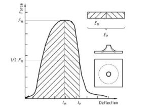
プラスチック – 硬質プラスチックの穿刺衝撃挙動の測定 – 一部 2: Instrument impact test Diagram 1
形 2 — Example force-deflection plot of failure by yield (zero slope at maximum force), followed by steady crack growth, and typical appearance of the specimen after testing (using lubrication)
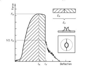
プラスチック – 硬質プラスチックの穿刺衝撃挙動の測定 – 一部 2: Instrument impact test diagram 2
形 3 — Examples of force-deflection plots through yield (zero slope at maximum force) and typical appearance (lubrication) failure of a tested specimen
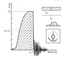
プラスチック – 硬質プラスチックの穿刺衝撃挙動の測定 – 一部 2: Instrument impact test diagram 3
Note that the natural vibration of the force detector can be seen after the unstable cracking (firing pin and weighing sensor).
形 4 — An example force-deflection diagram of an unyielding failure followed by unstable crack growth and a typical appearance of the specimen after testing (using lubrication)
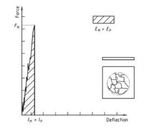
プラスチック – 硬質プラスチックの穿刺衝撃挙動の測定 – 一部 2: Instrument impact test diagram 4
標準情報部分のみ公開. 完全なコンテンツを表示するには, 公式チャネルを通じて標準を購入する必要があります.