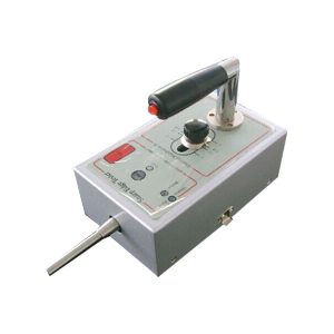
LR-47 GA-53 Photovoltaic ground impedance testing machine
- Description
- Inquiry
Description
Photovoltaic ground impedance testing machine
Product introduction
Specially designed for photovoltaic industry (solar water heater, solar panel, photovoltaic power generation system, etc.), the intelligent program-controlled safety code AC withstand voltage, DC withstand voltage, insulation resistance, grounding resistance tester is designed.
The minimum resolution of DC withstand voltage test current can reach 1NA and the maximum insulation resistance can reach 50g Ω. The test accuracy is ± 1.5%. It is easy to operate. The parameters of AC voltage withstand, DC withstand voltage, insulation resistance and grounding resistance can be set at one time. The four parameters can be tested only by pressing the start key once. The test speed is fast and the efficiency is high.
Application field: PV module and its wire and cable, connector and rectifier
Compliance with standard: UL1703-2014 IEC61730
Photovoltaic ground impedance testing machine
Performance characteristics
1. With Chinese and English display interface, it can meet the different needs of different users.
2. Constant voltage output: the adjustment rate of the output voltage is within ±1%, so as to avoid the output voltage change due to the unstable input power voltage and load change, and the measurement results are not accurate.
3. With the function of fast discharge, the tester can discharge the tested body and circuit within 0.2s of dc test, ensuring the safety of operators.
4. It has the function of open circuit detection in DC test, which can prevent misjudgment caused by test line falling off during DC test.
5. The current upper limit alarm and lower limit alarm functions can be set to prevent misjudgment caused by the test line falling off. The current offset function can eliminate the influence of the leakage current of the test fixture on the test results.
Unique performance
1. The safety electric wall and safety protection system can protect the operator’s safety and ensure that the tested parts are not damaged.
2. The standard sine wave is generated by DDS, and the output voltage is driven by linear power amplifier. The output voltage waveform is pure and the distortion is less than 2%.
3. Fast voltage build-up time:
(1) The establishment time of AC output voltage is 126 MS and that of DC output voltage is 60 ms.
(2) The minimum time between steps is 450 ms.
4. The frequency range of output AC voltage is 40.0hz ~ 400.0hz, and the resolution is 0.1Hz. It can be used as high voltage frequency conversion source. It is the only tester with continuous adjustable frequency in safety regulation industry. 5. The floating grounding mode can be selected. Grounding mode means that the current measuring end is connected with the shell, which is mainly used in the test system. Floating mode means that the current measurement end is suspended and not connected with the casing. This mode is applied to the occasions with high measurement accuracy. 6. It can automatically save the test results in the tester, which is convenient for users to check the test results; it can also be connected with RS232 interface to import the test results into excel table for data statistics and analysis.
Model | CS9933G-1 | CS9933G-2 | CS9933G-15 | |||||||||||||
CS9933G-4-15 | ACW | Output voltage | Range | 0.050kV~5.000kV | ||||||||||||
Accuracy | ±(1.5%read value +5V) | |||||||||||||||
Resolution | 1V | |||||||||||||||
Maximum output | ||||||||||||||||
100VA(5.000kV/20mA) | ||||||||||||||||
Maximum rated current | 20mA | |||||||||||||||
Lower current range | 0~20mA,0=not to judge the lower limit | |||||||||||||||
Current gear | ||||||||||||||||
200uA、2mA、20mA | ||||||||||||||||
Output waveform | Sine wave | |||||||||||||||
Output waveform distortion | ||||||||||||||||
≤2%(No load or pure resistive load) | ||||||||||||||||
Crest factor | 1.3~1.5 | |||||||||||||||
Output signal type | DDS+ Power amplifier | |||||||||||||||
Voltage rise time | ||||||||||||||||
0.3s~999.9s 0= Voltage rise time off | ||||||||||||||||
Test time | 0.3s~999.9s 0= Continuous test | |||||||||||||||
Voltage drop time | ||||||||||||||||
0.3s~999.9s 0= Voltage drop time off | ||||||||||||||||
Interval time | 0.0s~999.9s 0= Interval time off | |||||||||||||||
Output voltage mode | N mode、G mode | |||||||||||||||
DCW | Output voltage | |||||||||||||||
Range | 0.050kV~6.000kV | |||||||||||||||
Accuracy | ±(1.5%read value +5V) | |||||||||||||||
Resolution | 1V | |||||||||||||||
Maximum output power | 60W(6.000kV/10mA) | |||||||||||||||
Maximum rated current | 10mA | |||||||||||||||
Current gear | ||||||||||||||||
2uA、20uA、200uA、2mA、10mA | ||||||||||||||||
Ripple coefficient | ≤5% | |||||||||||||||
Discharge time | ||||||||||||||||
≤200ms | ||||||||||||||||
Maximum charging current | 10mA | |||||||||||||||
Voltage rise time | 0.3s~999.9s 0= Voltage rise time off | |||||||||||||||
Test time | ||||||||||||||||
0.3s~999.9s 0= Continuous test | ||||||||||||||||
Voltage drop time | 0.3s~999.9s 0= Voltage drop time off | |||||||||||||||
Interval time | ||||||||||||||||
0.0s~999.9s 0= Interval time off | ||||||||||||||||
Delay alarm time | 0.3s~999.9s 0= Delay alarm time off | |||||||||||||||
Output voltage mode | N mode、G mode | |||||||||||||||
IR | Output voltage | |||||||||||||||
Range | 0.500kV~2.500kV | 0.500kV~5.000kV | 0.500kV~1.500kV | |||||||||||||
0.500kV~1.500kV | Accuracy | ±(1.5%read value +5V) | ||||||||||||||
Resolution | ||||||||||||||||
1V | ||||||||||||||||
Maximum upper limit setting value | 50GΩ | |||||||||||||||
Maximum lower limit set value | 49.9GΩ | |||||||||||||||
Minimum lower limit setting value | ||||||||||||||||
5MΩ | ||||||||||||||||
Voltage rise time | 0.3~999.9s 0= Voltage rise time off | |||||||||||||||
Test time | ||||||||||||||||
0.3s~999.9s 0= Continuous test | ||||||||||||||||